| No.417 | Garbage data comes to my socket using RS485 communication. |
 |
26-03-2013 |
|---|---|---|---|
Category : can notSometimes, garbage data comes to socket because of electrical NOISE in RS-485 communication. Usually, the RX LED for a serial port looks ON. In this case, we recommend you solve it referring to the recommended circuit below. It is a general RS-485 network. 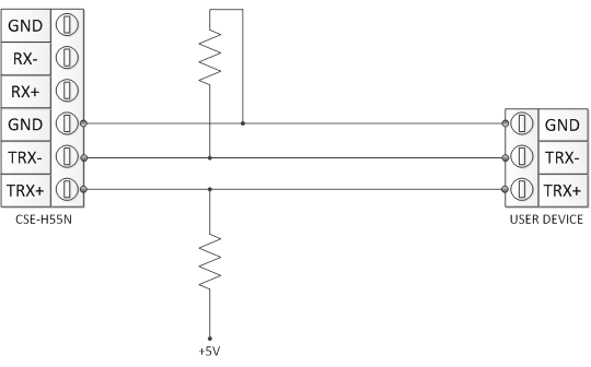
1. Signal GroundIf you don’t connect signal ground, there will be some noises or the receiver might be broken because of voltage difference between two devices. 2. Biasing Resistors (BR1, BR2)The biasing resistors make the voltage difference between the TRX+ and TRX- should be over +200mV when the RS-485 lines are idle. (No driver is driving.) If the voltage difference is under +200mV, the operation unpredictable. There might be some noise data during the idle state or during the data communication. Of course, the RS-485 driver has the “fail-safe” function for it. But it doesn’t work in some cases. (It happens randomly.) So the biasing resisters are needed for the RS-485 network. A. +5V There is a ground interface in ezTCP but the 5V is not available for the biasing resistors. (A 3.3V power can be used instead of 5V.) The biasing resistors can be at any points and only one pull-up and one pull-down resistors are enough. So you can place the resistors on the customer’s device side if a +5V pin is available. B. Pull-up / Pull-down resistors I recommend 680ohm or 560ohm for the biasing resistors but other values can be used if there is no termination resistor. If the value is becoming higher, the response time will get slower and the current will be decreased. On the other hand, if the value is becoming lower, the response time will get faster and the current will be increased. C. Some RS-485 devices embed biasing resistors. In this case, you don’t have to add any additional biasing resistors. (ezTCP does not have biasing resistor!) 3. Termination Resisters (TR1, TR2)If the cable is long or the transmission speed is high, two termination resistors are needed because there will be data corruptions by reflection waves. The termination resistors’ value should be the same to the cable’s characteristic impedance. Most cables’ characteristic impedances are 100 ohm or 120ohm. When you add only termination resistors without any biasing resistor, it might cause a problem. The usual termination resistances are 100 or 120 and there is internal pull-up resistance in the driver. So the differential voltage might be under +200mV, and it causes a problem. The resistance of the biasing resistors should be 560 ohm or 680 ohm in this case. - See also - Related Products
|
|||

|
#901-907, 869, Gyeongwon-daero, Michuhol-gu, Incheon 22134, Korea (Republic Of)
Tel. +82 32 245 2323 | Fax. +82 32 245 2327 | Email. sales@ezTCP.com